| Dial Indicators JIS B 7503: 2017 ( Japan Industrial Standards ) |
 Methods of measuring of performance Methods of measuring of performance |
| Measurement item |
Applicable type |
Measuring method
(Fixed zero method) |
Evaluation method
(Transferring zero method) |
Example of
measurement |
Error of
indication |
Error of
indication
over the
whole
measuring
range |
Dial gauge
with multiple
revolutions and
dial gauge with
partial revolution |
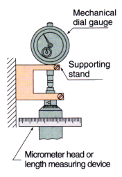
Fix the dial gauge rigidly in a
supporting stand, move the
contact element successively
in the forward direction, and
read the errors of indication a)
at the following measuring
points.
|
・ From the starting point to
2nd revolution, at every 1/10
revolution of the pointer b) |
・ From 2nd to 5th revolution,
at every 1/2 revolution of
the pointer |
・ From 5th to 10th revolution,
at every one revolution of
the pointer |
・ From 10th to 50th revolution,
at every 5 revolutions |
・ From 50th revolution
and onward, at every 10
revolutions |
After pressing in the contact
element so that the pointer
shifts by three or more scale
divisions from the end point of
the measuring range, move
the contact element in the
retrace direction successively
and read the errors of
indication at the same points
as measured in the forward
direction. |
|
Obtain the difference between the
maximum and minimum errors
of indication at all measuring
points in both forward and retrace
directions.
|
 |
Error of
indication
over 1/10
revolution |
Obtain the maximum value of
difference in errors of indication
between any two adjacent
measuring points at every 1/10
rotation from the starting point to
2nd revolution in both forward and
retrace directions. c)
|
Error of
indication
over 1/2
revolution |
Dial gauge
with multiple
revolutions |
Obtain the maximum value of
difference between the largest and
smallest errors of indication read
at every 1/2 revolution within the
measuring range from the starting
point to 5th revolution, in both
forward and retrace directions.
|
Error of
indication
over one
revolution |
Obtain the maximum value of
difference between the largest and
smallest errors of indication read
at every one revolution within the
measuring range from the starting
point to 10th revolution, in both
forward and retrace directions.
|
Hysteresis
Error |
Dial gauge
with multiple
revolutions and
dial gauge with
partial revolution |
Obtain the maximum value of
difference between errors of
indication taken in the forward
direction and those taken at the
corresponding measuring points in
the retrace direction.
|
| Repeatability |
Dial gauge
with multiple
revolutions and
dial gauge with
partial revolution |
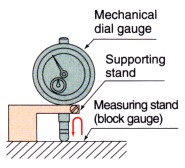
Fix the dial gauge in a
supporting stand, and after
pressing in the contact
element to a desired position
within the measuring range,
allow it to retract quickly or
slowly five times and take a
reading at each point. |
Determine the maximum difference
between the five indications
obtained. |
 |
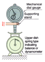
| Measuring force |
Fix the dial gauge in a
supporting stand, and move
the contact element in the
forward and retrace directions
continuously and gradually
and take measurements of
the measuring force at the
starting point and end point. |
Determine the maximum value of
the readings (maximum measuring
force) and minimum value of the
readings (minimum measuring
force) and also determine the
differences in the readings
between corresponding measuring
points in forward and retrace
directions. |
 |
|
|
|
| Notes |
a) |
For reading of errors, either read the input quantity of the measuring
device with the pointer of the dial gauge adjusted
at a scale graduation, or read the indication of the dial gauge according to the displacement of the measuring device. |
|
b) |
For dial gauge with partial revolution, read errors at every 10 scale divisions. |
|
c) |
For dial gauge with partial revolution, obtain the maximum value of difference
in errors of indication between any two
adjacent measuring points at every 10 scale divisions. |
|
|
|
|
|
| Dial Indicators JIS B 7503: 2017 ( Japan Industrial Standards ) |
Performance of vertical (standard type) dial gauges with bezel diameters not less than 50mm
[maximum permissible error (MPE)] |
| Performance |
Scale interval ( mm ) |
| 0.01 |
0.005 |
0.001 |
| Measuring range ( mm ) |
1 or
under |
Over
1 up
to and
incl. 3 |
Over
3 up
to and
incl. 5 |
Over
5 up
to and
incl. 10 |
Over
10 up
to and
incl. 20 |
Over
20 up
to and
incl. 30 |
Over
30 up
to and
incl. 50 |
Over
50 up
to and
incl. 100 |
5 or
under |
1 or
under |
Over
1 up
to and
incl. 2 |
Over
2 up
to and
incl. 5 |
Error of
indication
( MPE )
( μm ) |
1/10 revolution |
5 |
5 |
5 |
5 |
8 |
10 |
10 |
12 |
5 |
2 |
2 |
3.5 |
| 1/2 revolution |
8 |
8 |
9 |
9 |
10 |
12 |
12 |
17 |
9 |
3.5 |
4 |
5 |
| one revolution |
8 |
9 |
10 |
10 |
15 |
15 |
15 |
20 |
10 |
4 |
5 |
6 |
Whole
measureing
range |
8 |
10 |
12 |
15 |
25 |
30 |
40 |
50 |
12 |
5 |
7 |
10 |
Hysteresis error
( MPEH ) ( μm ) |
3 |
3 |
3 |
3 |
5 |
7 |
8 |
9 |
3 |
2 |
2 |
3 |
Repeatability
( MPER ) ( μm ) |
3 |
3 |
3 |
3 |
4 |
5 |
5 |
5 |
3 |
0.5 |
0.5 |
1 |
|
|
|
For the MPE of dial gauge with partial revolution, the error of indication over 1/2 revolution or one revolution is not specified. |
|
|
|
|
Performance of dial gauges with bezel diameters less than 50mm and horizontal
(back plunger type) dial gauges
[maximum permissible error (MPE)] |
| Performance |
Scale interval ( mm ) |
| 0.01 |
0.005 |
0.002 |
0.001 |
| Measuring range ( mm ) |
| 1 or under |
Over 1 up to
and incl. 3 |
Over 3 up to
and incl. 5 |
Over 5 up to
and incl. 10 |
5 or under |
1 or under |
1 or under |
Error of
indication
( MPE )
( μm ) |
1/10 revolution |
8 |
8 |
8 |
9 |
6 |
2.5 |
2.5 |
| 1/2 revolution |
11 |
11 |
12 |
12 |
9 |
4.5 |
4 |
| one revolution |
12 |
12 |
14 |
14 |
10 |
5 |
4.5 |
Whole measureing
range |
15 |
16 |
18 |
20 |
12 |
6 |
5 |
Hysteresis error
( MPEH ) ( μm ) |
4 |
4 |
4 |
5 |
3.5 |
2.5 |
2 |
Repeatability
( MPER ) ( μm ) |
3 |
3 |
3 |
3 |
3 |
1 |
1 |
|
|
|
For the MPE of dial gauge with partial revolution, the error of indication
over 1/2 revolution or one revolution is not specified. |
|
|
|
|
| Measuring force of mechanical dial gauge [maximum permissible limit (MPL)] |
| Performance |
Measuring range ( mm ) |
| 10 or under |
Over 10 up to
and incl. 30 |
Over 30 up to
and incl. 50 |
Over 50 up to
and incl. 100 |
| Maximum ( N ) |
2.0 max |
2.5 max |
3.0 max |
3.5 max |
| Minimum ( N ) |
To be defined by the manufacturer. |
| Hysteresis ( N ) |
|
