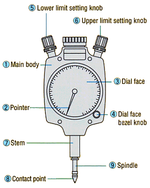
PEACOCK OZAKI MFG.CO.,LTD
 HOME > Product Information > Signal Indicators
Signal Gauge Set-Up / Connections Diagram


 Signal Gauge Set-Up
Model S-5, S-7, S-9 Signal Gauge ; How to Use
Signal Gauge ; How to Use

Instructions
a. Prepare a judgement master ( standard sample ) and hold
a signal gauge on a stand, etc.
b. Adjust and fix the position of judgement master so that
a gauge pointer indi-cates zero, and move the contact
point (8) up and down several times so as to confirm the
pointer's stable position.
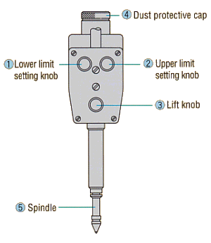
c. When setting a lower limit of tolerance value, remove
the master and turn the lower limit setting knob (5) so
as to adjust a pointer at a certain graduation.
d. When setting an upper limit of tolerance value, turn the
upper limit setting knob (6) so as to adjust a pointer at
a certain graduation while fully pushing up the contact
point (8).
e. After setting the upper and lower limit, move the spindle
(9) up and down ser-veral times to confirm that a
pointer's indication is within the tolerance value.
* Stem or back cover with lug is used to support the gauge.
Model SC-2A Signal Checker ; How to Use
Signal Checker ; How to Use Instructions
a. Prepare a judgement master ( standard sample ) and hold
a signal gauge on a stand, etc.
b. Prepara a dial gauge for setting tolerance value No.107
( 0.01mm to 10mm ) and remove the dust protective cap
(4) by a hexagon wrench attached to the gauge.
c. Turning the lift knob (3) allows the spindle (5) to move
up and down.
The pointer of dial gauge moves according to its
movement.
d. Connect this checker with a signal box or a controller.
e. Prepare a judgement master ( standard sample ), on which
push this checker to the position where the lower limit
of tolerance value can be set, and fix it by a supporting
device.
f. Set the indicator of dial gauge at zero of a dial and turn
the lower limit setting knob (1) fully in the clockwise
direction.
g. Set the upper limit of tolerance value at a certain
position while turning the lift knob (3) in the
clockwise direction.
h. Turn the upper limit setting knob (2) in order to adjust the indications ( signals ) of signal box or
controller to the switching position of OK and +NG at the upper limit of tolerance value.
i. Remove the master and turn the lift knob (3) in the counter clockwise direction to set the lower limit
of tolerance value.
j. Turn the lower limit setting knob (1) to adjust the indications ( signals ) of signal box or controller to
the switching position of OK and -NG at the lower limit of tolerance value.
k. Move the spindle (5) up and down several times by the lift knob (3) to check the right adjustment.
l. After your setting, turn the lift knob (3) in the counter clockwise direction until the spindle (5) is fully
pushed down.
m. When you use this checker without dial gauge, never forget to mount the dust protective cap (4) on it.
* Stem is used to support this checker.


 Signal Gauge Connections Diagram
Signal Gauge Connections Diagram

* Gauge are connected to a signal box by attached connectors.
When connecting with a signal controller or a sequencer, remove the connectors and use solderless terminals.


HOME | Product Information | Signal Indicators | INDEX: Model No. | Page Top |


Design and specifications are subject to change without notice for future improvement.


 Copyright(C) OZAKI MFG.CO.,LTD. All Rights Reserved.